
Honda Element engine parts diagram: system of compulsory ventilation of a crankcase and system of catching of steams of fuel diagrams for Honda Element 2.4. The full description of Honda Element system of compulsory ventilation of a crankcase, Honda Element system of catching of steams of fuel and all diagrams necessary for repair.
System of compulsory ventilation of a crankcase
The system serves for removal of the fulfilled gases which have broken from a combustion chamber in a crankcase of the engine. Ventilation is made by means of atmospheric air. Air gets to a throttle valve and on tubes gets to space under a cover of a head of the cylinder block. Further, on ports of the engine air gets to a crankcase. In an engine crankcase the breather in which the valve of system of compulsory ventilation of a crankcase is established that allows to exclude engine oil hit in the gas mixture which is taken away from a crankcase of the engine is made. The gas mixture on a tube gets back to an intake manifold behind a throttle valve (because of a difference of pressure before and after a throttle valve), and then in a combustion chamber that provides also original system of recirculation of the fulfilled gases and excludes possibility of blowout of crankcase fumes in atmosphere.
Diagram of system of compulsory ventilation of a crankcase: 1 - the valve of system of compulsory ventilation of a crankcase, 2 - a ventilating tube, 3 - an intake manifold, 4 - a ventilating hose.
System of catching of steams of fuel
The system of catching of steams of fuel prevents hit of steams of fuel from a fuel tank in atmosphere that provides fuller use of fuel as losses of fuel because of evaporation disappear. The system includes the accumulator of steams of fuel, the pressure control device, the 2-running valve, the valve of a blowdown, the accumulator of steams of fuel, an electropneumatic valve of the accumulator of steams of fuel, and also system of tubes and hoses. When pressure of steams of fuel in a fuel tank becomes high, the 2-running valve of system of catching of steams of fuel and the evaporated fuel opens arrives in the accumulator of steams of fuel where there is an accumulation of steams of fuel. The accumulator of steams of fuel accumulates steams of fuel by means of an adsorbing element.
Process of restart-up of steams of fuel occurs through an electropneumatic valve of the accumulator of steams of the fuel, steered a control package the engine. The electropneumatic valve works, when the cooling fluid temperature exceeds 55 degrees С.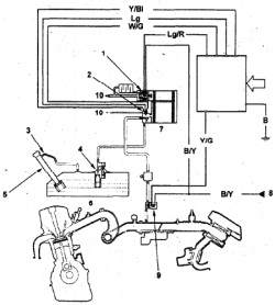 During the necessary moment in the accumulator of steams of fuel air from atmosphere moves, superseding steams of fuel from the accumulator, then the control package opens the valve of the accumulator of steams and pair are started up in an intake manifold behind a throttle valve, getting together with air in a combustion chamber. The control package, also, supervises size of opening of an electropneumatic valve of the accumulator of steams of fuel by means of the gauge of opening of the valve that allows to regulate quantity of restarted up fuel depending on turns. If in a fuel tank the depression exceeding admissible, the 2-running valve is created opens also fuel steams move back in a fuel tank.
Diagram of system of catching of steams of fuel: 1 - the valve of a blowdown of the accumulator of steams of fuel, 2 - the pressure control device, 3 - a tube, 4 - the valve, 5 - fuel-jellied a tube, in - a fuel tank, 7 - the accumulator of steams of fuel, 8 - from a safety lock #4 (10А), 9 - an electropneumatic valve of the accumulator of steams of fuel, 10 - atmosphere.